
Lately we have been hard at work developing a new robotic beer servant named Keg-a-Droid; you can check out our Kickstarter campaign. Keg-a-droid is a remote controlled, mobile robot equipped with a keg and tap system and this week’s Tech Thursday will demonstrate some components of the beer dispensing control system. More specifically, this is the test setup we used to calibrate our flowmeter output to fluid volume.
Components
Let’s cover the parts used:
Flowmeter – This is a hall-effect based flowmeter. It functions similarly to motor encoders: as fluid flows through the flowmeter, it generates digital pulses that can be counted to determine how much fluid has passed. On Keg-a-Droid, this component will be used to track how much beer has been dispensed.
Encoder Buffer Board (TE-183-002) – This component is used to count the flowmeter output pulses. It features a SPI interface and can easily be combined with an Arduino or other microcontroller.
LCD (LCD-013-420) – This is a 20×4 LCD with an I2C interface. We’re controlling it through the Arduino using the LiquidCrystal_I2C library (https://bitbucket.org/fmalpartida/new-liquidcrystal/downloads). Its current draw is low enough that it can be powered directly from the Arduino’s 5V bus. In this project it is used to display the flowmeter pulse count.
Solenoid Valve – This is just a valve that is opened and closed using a 24V, 150 mA solenoid. When the solenoid is unpowered, the valve is closed. When current flows through the solenoid, the valve is opened and fluid is permitted through. This allows us to electronically enable and disable fluid flow.
High Current TTL Driver (TE-010-800) – This component allows control over the solenoid valve. As the Arduino can’t provide the 24V and 150 mA needed to drive the solenoid, the high current driver has a 5V TTL input that enables or disables the solenoid’s connection to a 24V battery.
24V Battery – Used as the power source for the solenoid valve. On Keg-a-Droid, this is also the source for the drive motors.
Arduino Uno (MCU-050-000) – Control board used to open/close the solenoid valve through the high current driver, read flowmeter pulses from the buffer board, and write the data to the LCD.
Setup
The flowmeter calibration setup is shown in the figure below.
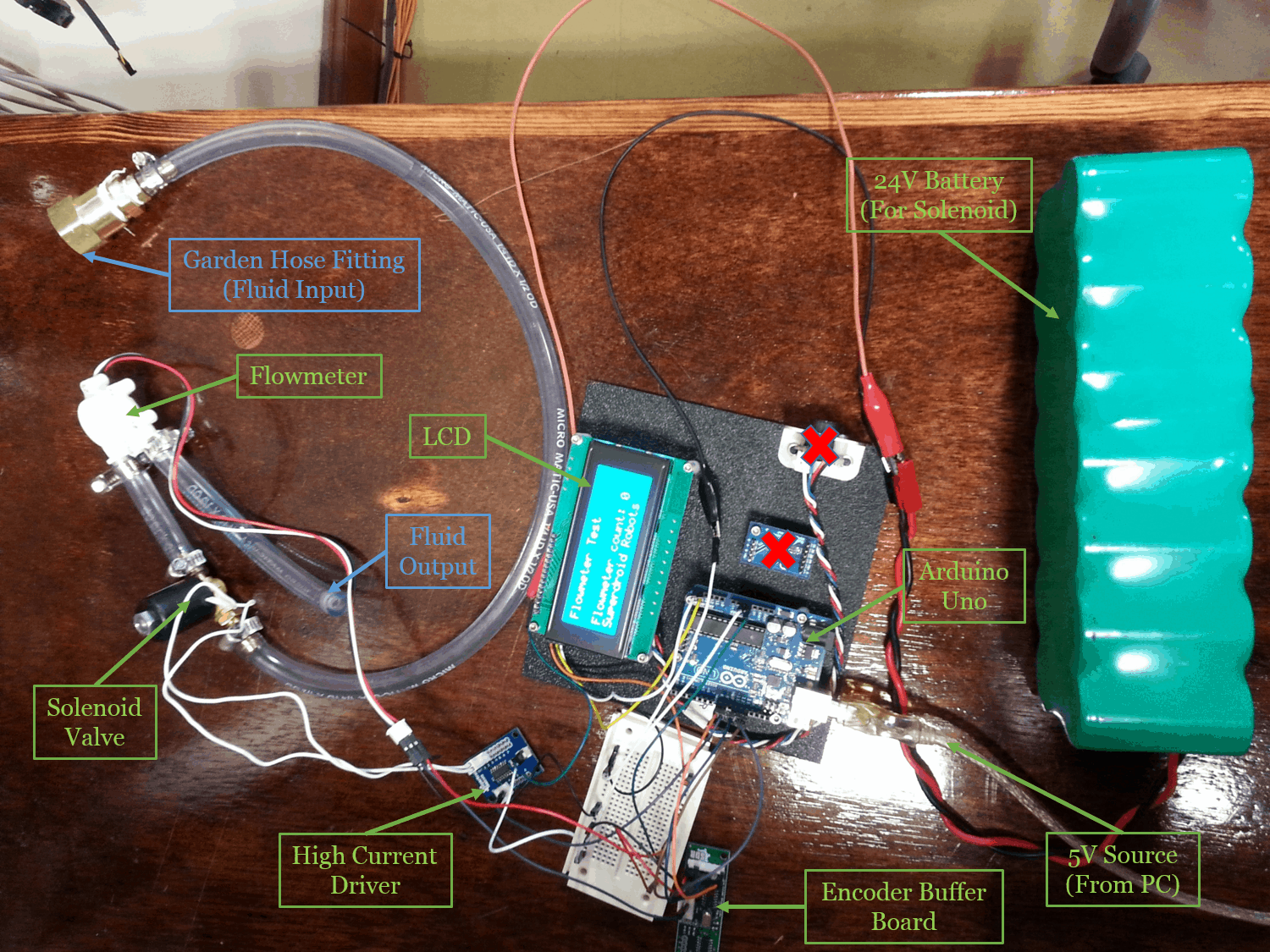
Figure 1: Flowmeter Calibration Setup
And here’s a functional schematic showing how the components are connected.

Figure 2: Functional Schematic
Note that this isn’t a true wiring schematic since some connections such as the 5V source and channel select line to the buffer board are omitted.
Arduino Code
The code below makes use of the LiquidCrystal_I2C library to talk to the LCD and the SPI library to read from the buffer board. On each loop iteration, it reads the flowmeter pulse count from the buffer board and outputs it to the LCD screen. The solenoid valve is enabled/disabled every ~5 seconds by setting the current driver’s enable pin to high/low. You can replace the solenoid enable logic to use e.g. an external button or a serial command from the PC. We actually used a barcode scanner and scanned specific barcodes to open and close the solenoid, but that code is not included here.
#include   // Comes with Arduino IDE
// Get the LCD I2C Library here:
// https://bitbucket.org/fmalpartida/new-liquidcrystal/downloads
// Move any other LCD libraries to another folder or delete them
// See Library "Docs" folder for possible commands etc.
#include
#include

/*-----( Declare objects )-----*/
// set the LCD address to 0x27 for a 20 chars 4 line display
// Set the pins on the I2C chip used for LCD connections:
//                    addr, en,rw,rs,d4,d5,d6,d7,bl,blpol
LiquidCrystal_I2C lcd(0x27, 2, 1, 0, 4, 5, 6, 7, 3, POSITIVE);  // Set the LCD I2C address

int slaveSelectPin = 8;
int solenoidValvePin = 9;
long valveSwitchCounter = 0, valveSwitchLoops = 500;
boolean valveOpen = LOW;

void setup()   /*----( SETUP: RUNS ONCE )----*/
{
  Serial.begin(57600);   //debugging
  InitEncoder();

  lcd.begin(20,4);   // initialize the lcd for 16 chars 2 lines, turn on backlight
  lcd.backlight(); // finish with backlight off

  //-------- Write characters on the display ------------------
// NOTE: Cursor Position: (CHAR, LINE) start at 0
  lcd.setCursor(0,0); //Start at character 4 on line 0
  lcd.print("Flowmeter Test");
  delay(100);
  lcd.setCursor(0,3);
  lcd.print("Superdroid Robots");
}

void loop()
{
  long flowmeterCount = ReadEncoder();
  pinMode(solenoidValvePin,OUTPUT);
  lcd.setCursor(0,2);
  lcd.print("Flowmeter count: ");
  lcd.print(flowmeterCount,DEC);

  // Open and close valve on ~5sec interval //
  valveSwitchCounter++;
  if(valveSwitchCounter >= valveSwitchLoops) {
    valveOpen = !valveOpen;
    digitalWrite(solenoidValvePin,valveOpen);
    valveSwitchCounter = 0;
  }
  delay(10);
}

// Methods for interfacing with encoder buffer board //
void InitEncoder() {
	// Set slave select as outputs
	pinMode(slaveSelectPin, OUTPUT);

	// Raise select pins
	// Communication begins when you drop the individual select signsl
	digitalWrite(slaveSelectPin,HIGH);
	SPI.begin();

	// Initialize encoder
	//    Clock division factor: 0
	//    Negative index input
	//    free-running count mode
	//    x4 quatrature count mode (four counts per quadrature cycle)

	// NOTE: For more information on commands, see datasheet
	digitalWrite(slaveSelectPin,LOW);        // Begin SPI conversation
	SPI.transfer(0x88);                       // Write to MDR0
	//SPI.transfer(0x03);                       // Configure to 4 byte mode
        SPI.transfer(0x00);                      // set to non-quadrature mode
	digitalWrite(slaveSelectPin,HIGH);       // Terminate SPI conversation
	ClearEncoderCount();
}

long ReadEncoder() {
	// Initialize temporary variables for SPI read
	unsigned int count_1, count_2, count_3, count_4;
	long count_value;

	// Read encoder
	digitalWrite(slaveSelectPin,LOW);      // Begin SPI conversation
	SPI.transfer(0x60);                     // Request count
	count_1 = SPI.transfer(0x00);           // Read highest order byte
	count_2 = SPI.transfer(0x00);
	count_3 = SPI.transfer(0x00);
	count_4 = SPI.transfer(0x00);           // Read lowest order byte
	digitalWrite(slaveSelectPin,HIGH);     // Terminate SPI conversation

	// Calculate encoder count
	count_value = (count_1 << 8) + count_2;
	count_value = (count_value << 8) + count_3;
	count_value = (count_value << 8) + count_4;
	count_value = -1*count_value;
	return count_value;
}

void ClearEncoderCount() {
	// Set encoder's data register to 0
	digitalWrite(slaveSelectPin,LOW);      // Begin SPI conversation

	// Write to DTR
	SPI.transfer(0x98);

	// Load data
	SPI.transfer(0x00);  // Highest order byte
	SPI.transfer(0x00);
	SPI.transfer(0x00);
	SPI.transfer(0x00);  // lowest order byte

	digitalWrite(slaveSelectPin,HIGH);     // Terminate SPI conversation
	delayMicroseconds(100);  // provides some breathing room between SPI conversations

	// Set encoder1's current data register to center
	digitalWrite(slaveSelectPin,LOW);      // Begin SPI conversation
	SPI.transfer(0xE0);
	digitalWrite(slaveSelectPin,HIGH);     // Terminate SPI conversation
	delayMicroseconds(100);  // provides some breathing room between SPI conversations
}
// end of buffer board methods //
#kegadroid #encoders #arduino #techthursday
Hellow my name is MartinAudiz. Wery good-hearted post! Thx :)