How to Configure a RoboClaw Motor Controller with Velocity Control
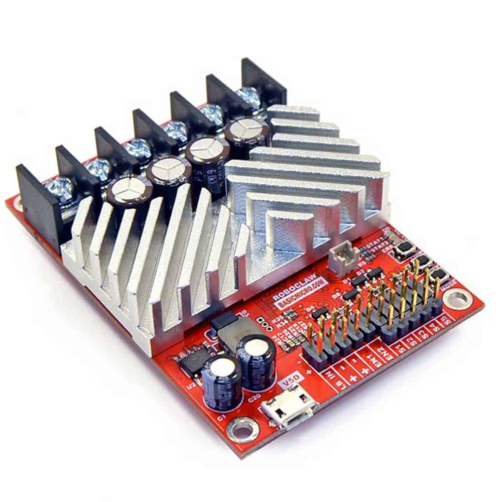
In this example we are going to show how to configure a RoboClaw Motor Controller with velocity control. We used two RoboClaw 2x7A Motor Controllers in one of our Mecanum robots.
The following images show the settings we used in each motor controller.


 <
<

Velocity Calibration Procedure
1. Determine the quadrature pulses per second (QPPS) value for your motor. The simplest method to do this is to run the Motor at 100% duty using Ion Studio and read back the speed value from the encoder attached to the motor. If you are unable to run the motor like this due to physical constraints you will need to estimate the maximum speed in encoder counts the motor can produce.
2. Set the initial P, I and D values in the Velocity control window to 1, 0 and 0. Try moving the motor using the slider controls in IonMotion. If the motor does not move it may not be wired correctly or the P value needs to be increased. If the motor immediately runs at max speed when you change the slider position you probably have the motor or encoder wires reversed. The motor is trying to go at the speed specified but the encoder reading is coming back in the opposite direction so the motor increases power until it eventually hits 100% power. Reverse the encoder or motor wires (not both) and test again.
3. Once the motor has some semblance of control you can set a moderate speed. Then start increasing the P value until the speed reading is near the set value. If the motor feels like it is vibrating at higher P values you should reduce the P value to about 2/3rds that value. Move on to the I setting.
4. Start increasing the I setting. You will usually want to increase this value by .1 increments. The I value helps the motor reach the exact speed specified. Too high of an I value will also cause the motor to feel rough/vibrate. This is because the motor will overshoot the set speed and then the controller will reduce power to get the speed back down which will also undershoot and this will continue oscillating back and forth from too fast to too slow, causing a vibration in the motor.
5. Once P and I are set reasonably well usually you will leave D = 0. D is only required if you are unable to get reasonable speed control out of the motor using just P and I. D will help dampen P and I overshoot allowing higher P and I values, but D also increases noise in the calculation which can cause oscillations in the speed as well.
In the next image you can see the motors following the commands from the Arduino.

We experience that velocity control helps the robot drive straighter. In the next video you can see the robot performance with velocity control using RoboClaw Motor controllers.
Mecanum Robot with RoboClaw Motor Controller with Velocity Control
Supporting Documentation
- You can consult Roboclaw user manual if you have more questions: RoboClaw User Manuals
- Code used to interface the RoboClaws: Sample Code on Github
- RoboClaw Library: Arduino Library and Examples
- Here is the schematic of the robot: Mecanum Robot Schematic

