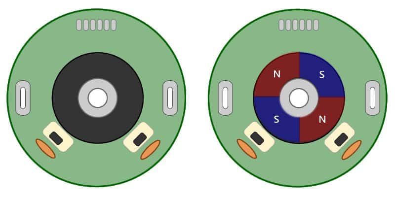
One of the most basic positioning elements of autonomous robotics is the encoder. These are attached to rotating points such as arm joints and wheel axles in order to determine distance of movement. We sell an array of our IG32, IG42, and IG52 gear motors with a hall-effect encoder option.
How do they work?
The picture above is a simple diagram of the hall-effect encoder found on the back of our motors. The dark center mass is a round magnet that is fixed to the rear shaft of the motor. As it spins the sensors pass the symmetrically placed hall-effect sensors. As the north pole passes the sensor, it will trip and connect that channel output to ground. This produces the waveform seen below.
From these pulses we can calculate movement by watching the the changes in the voltage levels of each encoder channel. The importance of having two channels that are offset about 90 degrees is that we can infer the direction of the motor by which channel is leading (goes from low to high first). This allows us increment or increment our encoder counts properly.
How to interface with the encoder
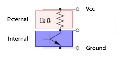
The hall-effect encoders that we use require external circuitry to function properly. As seen in the datasheet on the individual product pages, you will need to add a 1-kOhm pull-up resistor to each output channel. This is because the sensors ground out the output signal when the appropriate pole of the magnet passes the sensor.
Interfacing a microcontroller directly to the encoder is not recommended. It is possible to continuously check two digital inputs for their values and keep track of your encoder counts but the main issue is timing related, especially with encoders with high counts-per-revolution (CPR) or higher speeds. Unless you are able to continuously check these inputs you are going to miss counts. Simple commands such as a Serial.print() on an Arduino, are time intensive enough to cause missed counts even at moderate speeds. This is why we highly recommend our LS7366R breakout. These chips monitor the encoder pulses for you and provide a simple SPI interface so that you can request the current encoder counts when you need them. They also already have the appropriate pull-up resistors to reduce the need for wiring.
If you have your own solution that you want to use. We also sell stand-alone pull-up boards with the appropriate resistors to make wiring easier.
Determining the Counts Per Revolution (CPR)
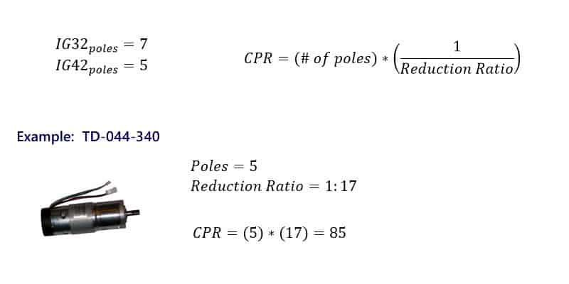
The datasheet for our encoder enabled motors are general and cover a wide range of motors. As such, the datasheet can be confusing to determine the expected CPR of the selected motor. Please refer to the formula below and the product page for our IG42 340 RPM motor (TD-044-340).
From the datasheet we can see that the number of magnetic poles of a 32mm motor are 7 and the number of poles on the 42mm motor are 5. This tells us that we are going to see 5 or 7 encoder pulses for each complete rotation of that motor shaft. This is not the CPR of encoder because all of the motors that we sell are geared in some fashion.
When you gear a motor it changes the relation of the motor shaft that our encoder connects to and the output shaft that the wheel attaches to. This means that the number of turns of one is not the same as the other. This relation is known as the reduction ratio. Take, for example, the motor example below for the IG42 340RPM motor. This has a reduction ratio of 1:17. This means that the rear shaft of the motor spins 17 times per one rotation of that output shaft. Because of this we are going to need to multiply this ratio by the number of poles to get our full count.
#techthursday #encoders #gearmotors


